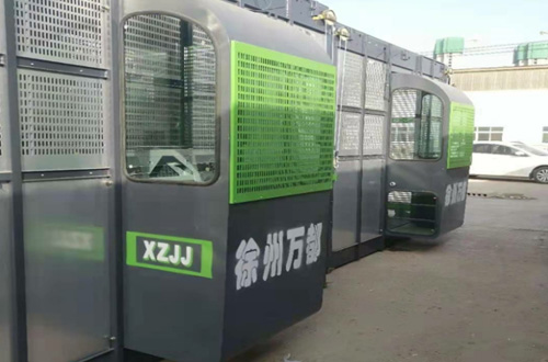
Machine debugging
After the main body of the elevator is in place, the height of the guide rail frame is installed to 6m, and the power-on trial operation should be carried out. First, confirm whether the power supply of the construction site is sufficient, the leakage protection switch in the construction site electrical box should be of impulse wave non-action type, and then check the rotation direction of the motor And whether the start brake is normal, whether the error protection, emergency stop, limit, upper and lower limit, deceleration limit, and each door limit switch are normal.
The elevator installation must be installed in accordance with the requirements of the "Elevator Installation" chapter of the manual, and every time an attached wall is installed, the verticality of the guide rail frame must be checked whether it meets the requirements
Debugging of roller backlash
Adjust the waist roller eccentric wheel of the transmission trolley and the cage to make the two cage columns and the transmission mechanism symmetrical with respect to the standard section, and the gap between each waist roller and the standard section riser is 0.6mm, and then tighten the waist roller bolts.
Gear and rack meshing clearance adjustment
Use lead pressure method to check the meshing gap of all racks and gears. The gap is required to be 0.3~0.5mm (the rack and pinion gap on the transmission trolley should be slightly smaller than the rack and pinion gap on the anti-drop gear version), otherwise the position of the size plate should be adjusted , In order to adjust the meshing gap of the rack and pinion, and then tighten all the large and small plate bolts.
Adjustment of the gap between the guide wheel and the rack
Use a feeler gauge to check the gap between all guide wheels and the back of the rack. The gap is required to be 0.5mm. Otherwise, adjust the guide wheel eccentric sleeve to adjust the gap between the guide wheel and the rack, and then tighten the guide wheel bolts.
Debugging of cable trolley and cable trolley
Place the cable trolley or cable trolley on the ground, adjust the waist roller eccentric shaft of the cable trolley or the cable trolley guide wheel. The gap between each roller and the corresponding track is required to be 0.5mm. Try to push and pull the trolley or cable trolley by hand without jamming.
Note: When installing and adjusting the bottom of the cage, the main power supply must be cut off first, and the bottom of the cage is supported on the two steel beams on the side of the guide rail with a rigid support to prevent the cage from falling down.
Upper and lower limit touch iron, limit switch touch iron and deceleration limit touch iron
Upper limit collision iron: use the cage top operation, run the elevator to the upper end of the uppermost transmission trolley and stop at the intersection of the third and fourth sections from top to bottom, and press the emergency stop button. Install the upper limit bumper so that the lower end of the bumper is flush with the third section of the standard section frame from the top, and tighten the bumper. Install the upper limit bumper and the limit bumper side by side, and the upper limit bumper is 250mm lower than the limit bumper. Fix the bumper with hook bolts, unscrew the emergency stop button, and check whether the upper limit and limit switch are functioning and can be disconnected normally.
Lower limit bumper, lower limit bumper, and deceleration limit bumper: use the cage to operate the elevator until the bottom of the cage is about 30mm above the outer cage door fence, press the emergency stop button, install the lower limit bumper, lower The limit touch iron, the frequency conversion model must be equipped with a deceleration limit touch iron. The operation method is as follows: first install the lower limit bumper: when the lower limit travel switch is required to control the cage to stop, the cage bottom plate should be about 30mm higher than the outer cage threshold under no load, and then install the lower limit bumper: lower limit When the top of the limit bumper is lower than the top of the lower limit bumper, when the lower limit travel switch is required to control the cage to stop, the lower limit switch's bump handle is about 100mm from the limit bumper; the frequency conversion elevator is installed with a deceleration limit bumper, and the deceleration limit bumper The top of the iron is about 400mm higher than the top of the lower limit toucher. It is required that when the deceleration stroke is 400~600mm, the lower limit travel switch starts to touch the top of the lower limit toucher. At this time, stop for installation. After installation, tighten all the touchers Fix the bolts, and finally carry out the driving test of the lower limit of the cage, and the installation of the lower limit device is finished. Unscrew the emergency stop button and check whether the lower limit and deceleration limit are working properly.
Speed debugging
The frequency-conversion speed-regulating elevator must be operated within a height range of 30m from the ground under the guidance of the manufacturer. Adjust the parameters of the frequency converter according to (adjust the frequency converter instruction manual) until the elevator running speed reaches the specified value.
No-load test
Each cage shall be subjected to no-load test separately, and the no-load test shall be carried out with a stroke of no less than 3 working cycles, and no less than two braking shall be carried out during the lifting and lowering process of each working cycle, and observe whether there is slip phenomenon during braking. , Confirm that all door switches are flexible.
Rated load test
Each cage should be subjected to a rated load test: the center of gravity of the load is located according to the inner and outer deviations, according to the working system of the selected motor, the inner and outer deviations are each tested for a full stroke of continuous operation for 30 minutes, the first working cycle The lifting process should be braked at least once.
No-load test
Overload test 125% of the rated load, the load is evenly distributed in the cage, the working stroke is the full stroke, and the working cycle is not less than three. The lifting process of each working cycle should be braked not less than once, and confirmation is required at the same time Whether the overload protector is working properly.
Fall test of anti-falling safety device
Carry out the drop test according to the requirements in the drop test chapter of the manual, and carry out the adjustment and recovery of the anti-fall safety device according to the requirements in the anti-fall safety device chapter.
Overload protection
Perform zero point adjustment and lifting weight display adjustment according to the requirements of the operating instructions of the overload protector
Full lubrication of the elevator
Lubricate according to the requirements in the lubrication chapter of the manual
Comprehensive inspection of the lift
Perform a comprehensive inspection according to the handover inspection certificate to ensure compliance with the inspection certificate, the commissioning of the whole machine is completed
Periodic inspection of lifts
Check regularly according to the requirements in the section of regular check in the manual, and debug or replace parts immediately if there is any problem.


